
Introduction
Tick-tock-tick-tock .............
The so much common sound which makes everything proceed in order. But have you ever wondered that how was the idea of keeping track of time concieved and how did the clock come into existence?
Well, we will confine ourselves to the study of pendulum clocks. They were the first clocks made to have any sort of accuracy. It is believed that the idea of using a pendulum in order to keep track of time was conceived by a Dutch astronomer, Christian Huygens, in 1656. But it was Italian mathematician, Galileo who, after observing the motion of a chandelier swinging over the altar in Pisa Cathedral in 1584, suggested the use of pendulums. He observed an interesting property of pendulums- the time-period (T) of a pendulum's swing is related only to the length (l) of the pendulum and the acceleration due to gravity (g). So, once 'l' is fixed, 'T' becomes constant as 'g' at a place is fixed.
The clock we have here is a German built 1910 model. It uses torsional
spring to store energy and primarily consists of two gear trains. The details are discussed below.
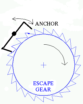
Escape Mechanism
COMPONENTS :-
Component--------------Quantity
Torsional Spring------------1
Gears-(B,D,F,H,J)-----------5
(Teeth)
N(B) = 84
N(D) = 60
N(F) = 40
N(H) = 40
N(J) = 35
Needle Gears-(C,E,G,I)-------4
(Teeth)
N(C) = 8
N(E) = 8
N(G) = 7
N(I) = 7
Dog Gear-A--------------1
Anchor------------------1
Pendulum bob-------------1

Hands Driving Mechanism
COMPONENTS :-
Component----------------Quantity
Gears-(D,L,P,N,M)-----------5
Teeth
N(D) = 60
N(L) = 26
N(P) = 36
N(N) = 9
N(M) = 36
Needle Gear-(K)-------------1
N(K) = 12
Tubular shafts(for hour & minutes hands)
WORKING :-
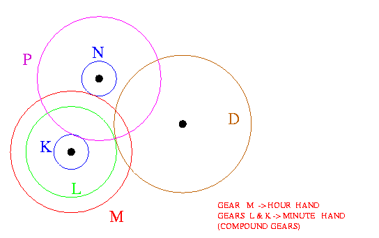
As the spring unwinds, simultaneously with the escape mechanism,hands-driving mechanism also works. Gear D moves the gear L which has gear K compounded to it. They correspond to the motion of the minute hand. Now K transfers the motion to P,P to N and N to M.The gear M is for the motion of the hour hand.
The hour and the minute hands are on different axes.For this reason tubular shafts are used on the gears ,and then the gear trains are arranged so that the gears driving the hour hand and the minute hand share the same axis.The tubular gear shafts are aligned one inside the other.
The point to be noted here is:
*Motion to only minute hand is given independently and it is the minute hand which drives the hour hand through a gear train.This has been done to ensure proper coherence between the two hands.
CALCULATIONS :-
From figure and data
[Using w[1]=w[2]*(N[1] / N[2])
w[M]=w[K]*(12/36)*(9/36)
w[M]=w[K]*(1/12)
Hence,angular velocity of hour hand is one-twelth of minute hand.
Alarm Mechanism
COMPONENTS :-
Component--------------------------Quantity
Torsional Spring-------------------------1
Gears-(B',E',F',I',K')---------------------5
(Teeth)
N(B') = 87
N(E') = 13
N(F') = 49
N(I') = 60
N(K') = 60
Needle Gears-(D',G',J',L')-----------------4
(Teeth)
N(D') = 8
N(G') = 8
N(J') = 6
N(L') = 7
Dog Gear-A'--------------------------1
Special Gear-C'------------------------1
Hammer-----------------------------1
Alarm spring--------------------------1
Arms-------------------------------3
Anchor-A'---------------------------1
Double-grooved plate--------------------1
Small plate with diagonally opposite projections-1
WORKING :-
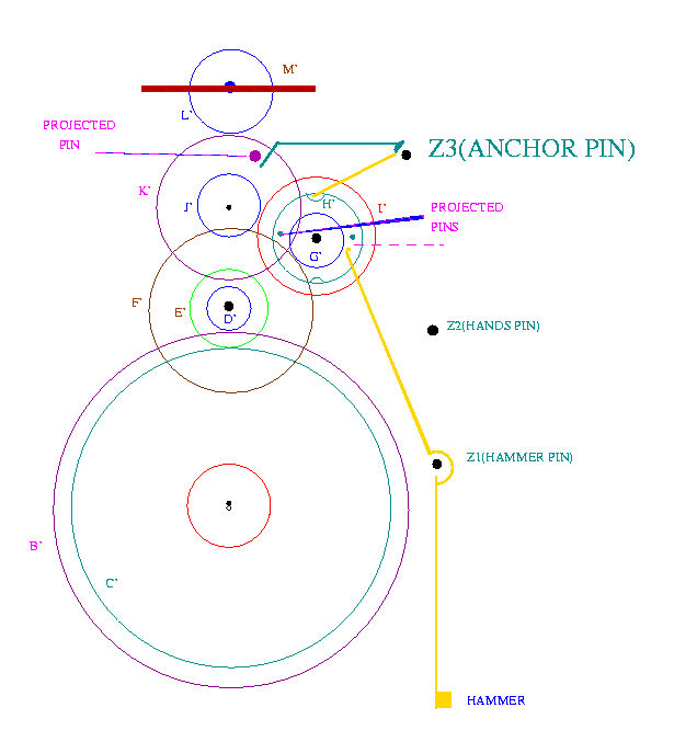
Like the time keeping mechanism ,here too we have a torsional spring ( to store energy ) with a dog gear which engages with the gear train when the clock rings alarm.
Now as the spring unwinds, gear B'starts rotating. This transfers the motion to needlle gear D'. E' & F'are also compounded on the same shaft. The motion is thus transferred to needle gear G'.Here we have a double grooved plate,the grooves being opposite to each other.
To know the working focus on the rod Z3-Z3' which is provided with 3 arms.One of them rests on this double grooved plate.As this plate rotates and the arm encounters a groove ,it, in order to maintain contact with the plate, follows the groove. In doing so it brings into motion the anchor(A') which rests on special gear C' .So now with the rotation of the double grooved plate this anchor starts oscillating. The gear C' on which it rests is specially designed to serve the purpose of the kind of alarm in this clock. The alarm is such that it rings 'n' times at 'n' o'clock like two times at 2 O'clock and also once every half past an hour.
On looking at the construction of this special gear ,we find that after every few shallow teeth their is a pair of deeper ones. Every time the anchor enters a shallow tooth,it makes the hammer(which is controlled by two projected pins on the double grooved plate) vibrate once, which results in the hammer hitting a spring, and we hear the alarm. Now this ringing continues till the anchor comes to a still. And this happens when the anchor enters a deeper tooth on the gear C'.(The grooves on the double grooved plate are deep enough only to get the anchor out of the shallow teeth. Once it is engaged in the deeper one, it brings the whole mechanism to a halt.
A couple of things to be noted here are:
* What is the purpose of adding the gears J',K',& L'& plate M'?
These 3 gears are present only to drive the plate M'.Now this plate, while rotating, acts
against friction (air resistance ) and hence
slows down the unwinding of the
spring. The work of this plate is analogous to the work of the anchor in the time k
eeping mechanism i.e. to make the energy stored in the spring last longer.
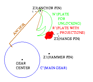
* A problem is that once the anchor enters
a deeper tooth how do we
lift it up and move again and that too after half an hour?
This is supervised by a hook
attached to a small plate,compounded with minute hand of the clock,which has tw
o diagonally opposite projections on it. Now when the alarm stops, after exactly
half an hour, one of these projections raises this hook which in turn raises th
e anchor and the whole procedure is repeated.
CALCULATIONS :-
From figure and data angular velocities are
w[G']=w[C'] * (87/8) * (49/8) = 66.6w[C']
w[L']=w[B'] * (87/8) * (49/8) * (60/6) * (60/7) = 5709.375w[B']
This shows that plate M' is made to rotate at a pretty high speed to ensure that we don't have to rewind the spring every now and then.
Comments on Components
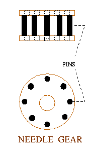
Now we discuss the utility of the various parts employed in the machine:
Suggestions
Some of the suggestions/modifications which we could think of while working on our project may be listed as follows:
The shafts on which the gears are mounted are rotating in two holes.Now due to constant wear and tear involved,the holes might get larger resulting in a loss of precision.Hence ,what may be suggested is the use of glass bearings because glass is highly wear resistant. It can break if highly stressed but won't loosen, this way we can continue by only changing the bearing (in case it breaks away ) and not the whole metal plate.In fact glass bearings are used now and measured in terms of jewels ( more the jewels better is the quality ).