
  |
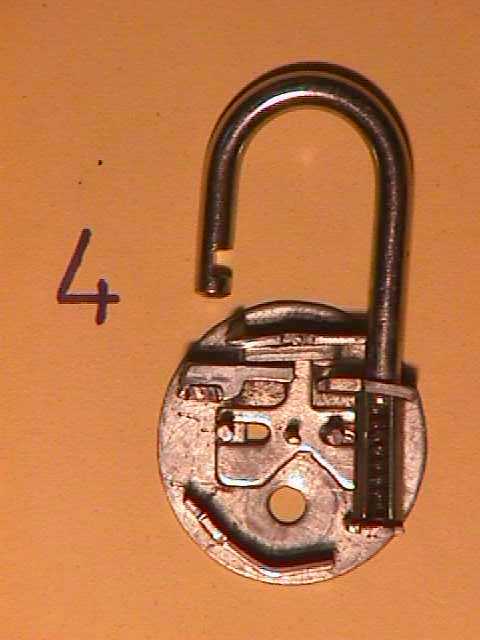
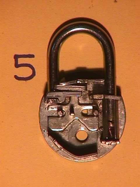
FIG.4 & FIG.5 SHOW THE OPEN and LOCKED configurations respectively of the lock with only the bolt (main lever/lever 1) in it's position. When the bolt and hence the engaging plate are in their rightmost position, The lock is in the "open" mode. when the key is rotated in anticlockwise direction, It pushes the blot and hence the engaging plate with the help of it's first projecting bit to their left most position. In this position the engaging plate engages with the slot in the hook and this is the "locked" mode.
  |
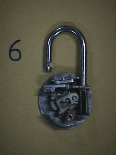
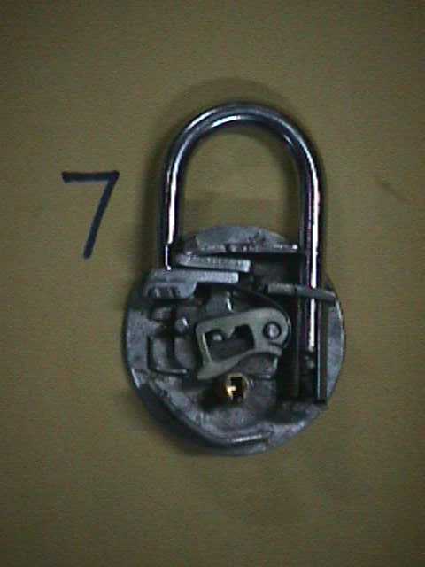
FIG.6 & FIG.7 SHOW THE OPEN and LOCKED configurations respectively of the lock with all the SEVEN LEVERS put in their respective order. as can be observed from the fig.6 the projecting pin of the bolt is engaged with the notches formed on the undersides of the other levers. The lock is in open mode when the pin is on the right side of the notches. When the key is rotated in anticlockwise direction, The projections of the bit raise all the variously shaped levers by an exact specified amount giving a clear passage for the pin through the slot. The bolt and hence the engaging plate are then pushed by the key as explained above to their right most position, Hence "locking" the lock.