Synthesis of Special Type
of Stepheson's Six-Bar Mechanisms
&
Analysis of Higher Pair Mechanisms
|
Gaurav
Shukla (95112)
Project Proposal : ME 751 Computer
Aided Engineering Design
Indian Institute of Technology
- Kanpur : November 1998
This
report is divided into two parts -
Contents
Motivation
Rocking motion produced by the "rocker"
of the four bar mechanism
has various applications. Four bar mechanisms
cannot give rockers
with rocking angle more than 180 deg.
with a restriction that
mechanism must have a crank for providing
input motion. Six bar
mechanisms are being explored for the
solution of this problem.
So for only qualitative proof is available
that a rocker with rocking
angle more than 360 deg. is possible
to configure with the help of
Stephenson's mechanism.
Past
Work :
Synthesis of four bar mechanisms has already
been studied in great
depth. Though some efforts have been
made for developing
methodologies for synthesis of six bar mechanisms
but still this is
an fairly unexplored area. Several methods
have been reported for
both kinematic analysis and synthesis of
planar six link mechanisms
[1-5]. Optimum solutions of six link function
generators including
the effects of tolerances in the link-lenghts
and clearances in the
joints have also been attempted [6]. Kinematic
synthesis of Watt-I
mechanisms generating closed coupler curves
with up to four cusps
has been formulated properly [5]. This can
be very useful to this
project. Stationary configurations of planar
six bar kinematic chains
have been studied fully [7].
Examples :
Following figure shows a Stephenson's mechanism whose synthesis is aimed
at in this project.

Sample
Input-Output :
In this project, efforts will be made
to develop a special type of
Stephenson's mechanism. In these mechanisms
ternary link will be
frame (Fixed). Three binary links will
be connected to this frame.
One of the binary links will be
a normal crank and one of them
will be a rocker with rocking
angle more than 360 deg. . Its rocking
range in the clockwise and anti clockwise
directions will be different.
One will exceed by 360 deg. from the
other.
Input :
1. Maximum Link Length
2. Rocking Range of The Rocker
e.g. 60 deg. to 90 deg. in
clockwise direction
and 60 deg. to 450 deg. in
anti clockwise direction
Output :
Stephenson's six bar mechanism in which one
binary link
out of three connected to a ternary
link, will be a crank
and one will rock more than 360
deg.
Methodology
:
First,
the problem of the synthesis was thought as a problem of path generation.
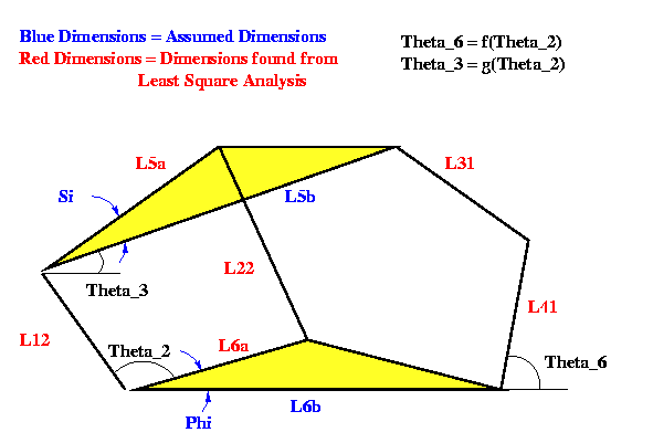
The Six-bar was divided in to two parts (as shown in the figure). A fictitious
coupler curve was generated according to requirements imposed by input-output
relationship of the desired mechanism. Corresponding, 4-bar was generated
by
path generation synthesis. The implemented method for this synthesis was
inspired from the paper "A Simple Approach For Optimum Synthesis
Of A
Class Of Planar Mechanism". The method suggested in the paper uses
non-derivative and quasi-Newton methods in series for search while the
implemented method depends upon derivatives of error terms with respect
to
link lengths which are used in the Least Square search.
Problem of convergence was encontered in this method. Least square search
may
not stop at all for a given input.

Alternatively, the problem can be solved by function generation. Standard
method of optimisation is used for finding the mechanism. This method is
adopted from the book "Kinematic Analysis and Synthesis of Mechanisms".
In this method, four parameters of the six-bar need to be assumed. Rest
of
the six parameters are found by least square analysis. In this method,
two
rotation angles need to be assumed as function of a crank angle. The angle
of the output link (i.e. link # 41) which is called "theta_6" is governed
by
angle of input link (i.e. link # 12) which is called "theta_2". The functionality
is decided by the desired mechanism. In addition to this, "theta_3" (angle
of floating link) is also required to be expressed as a function
of theta_2.
These are called the guess values. A cubic function which can qualitatively
satisfy the characteristics of the desired mechanism has been fitted for
these
guess values. Qualitative graphs of the two functions are shown in the
following figure.

The following loop closure equation form the basis of the least square
analysis.
l6b*l6b + l41*l41 + l5b*l5b - l31*l31
+ 2*l6b*l41*cos(theta_6)
- 2*l12*l6b*cos(theta_2) - 2*l6b*l5b*cos(theta_3+Si)
- 2*l41*l5b*cos(theta_6-theta_3-Si)
- 2*l41*l12*cos(theta_6-theta_2)
+ 2*l12*l5b*cos(theta_2-theta_3-Si) = 0 |
l12*l12 + l5a*l5a + l6a*l6a - l22*l22
+ 2*l12*l5a*cos(theta_2-theta_3)
-2*l6a*l12*cos(theta_2-Phi)
- 2*l6a*l5a*cos(theta_3-Phi) = 0 |
Ideally the left side of the two equations should be zero but it will
not be so for the given design points. So these two equations will
constitute error terms. These error terms will be minimised in the
least square sense over all design points.
Results :
The
function generation method as discussed in the methodology has been
implemented but it is not able to synthesize desired type of the mechanisms
even after 25 iterations of Least Square method which is supposed to be
very powerful search method. It is because of the "Guess Values". The
function fitted for these guess values is probably orienting the search
in
wrong direction from the beginning itself.
The possible remedy for the problem
is to identify the correct type of function for these guess values which
will definitely have some relationship with the input-output functional
relationship.
Bibliography
:
@Article{Shukla/Mallik :19__,
Author = {Gaurav Shukla and A. K. Mallik},
Year = {19__},
Institution = {I.I.T., Kanpur},
Title = {Detection of A Crank in Six Link Planar Mechanisms},
Annote = { When a ternary link of
Stephenson's mechanism
is fixed to the ground, there are three
binary links attached to it.
Due to the complex nature of the
coupler curve generated by the
point "E" (as shown in Fig. 1) link
"CD" can exhibit special type
of motion characteristics. This link can
oscillate more than 360
deg. This is proved in this paper through
a numerical example. }}
@Article{Cossalter/Doria:1992,
Author = {V. Cossalter and A. Doria and M. Pasini and C. Scattolo},
Year = {1992},
Institution = {University of Padova, Padova I-35131, Italy;
Nuovo Pignone SMIT, Schio, Italy},
Title = { A Simple Numerical Approach for Optimum Synthesis of a
Class of Planar Mechanism },
Volume = {Vol. 27, No. 3},
Journal = {Mech. Mach. Theory },
Pages = {357-366},
Annote = { In this study a numerical method for optimum synthesis of
planar mechanisms, generators of functions, paths and rigid motions, is
presented. Design parameters have wide variability range, inside which
first guess, demanded by the iterative minimisation procedure, can be
chosen at random. Kinematic analysis is carried out by decomposition
of the mechanism in to Assur groups; mechanism assembly is managed
by the construction of a proper penalty function. Optimisation is carried
out by using a non-derivative and a quasi-Newton method in series. }}
References
:
1 . Kinematic Analysis And Synthesis of Mechanisms
by, A. K. Mallik, Amitabha Ghosh, Gunter Dittrich
2 . Sakamoto, Y., Ogawa, K. and
Funabshi, H. Mech. Mach. Theory
29, 345-356 (1994)
3 . Bagci, C. Proc. I. Mech.
E 189, 855-859 (1975)
4 . Chung, W. Y. and Chiang,
C. H. Mech. Mach. Theory 25,
417-426 (1990)
5 . Cossalter, V., Doria, A., Pasini
M. and Scattolo, C. Mech. Mach.
Theory 27, 357-366 (1992)
6 . Chang, C. and Hwang, W. Mech.
Mach. Theory 29, 501-511 (1994)
7 . Husing, M. Dr. Ing. Dissertation,
T. H. Aachen (1995)
Contents
Motivation :
It is very easy to solve a problem
of path generation using a higher
pair joint (i.e. Cam) because in this
case only implementation of the
solution is required. On the other
hand, it is very difficult to solve the
problem of path generation using linkages
because here it amounts
to solving an inverse problem. This
is the reason of popularity of
higher pair mechanisms in industry. Though
they are expensive. So,
it is extremely essential to have software
packages which can handle
analysis of higher pair mechanisms in general.
Past
Work :
Analysis of cams is a direct problem
(i.e. given the complete configu-
ration of the mechanism, it is easy
to analyze and animate the
mechanism either analytically or numerically).
Analysis of typical roller
follower, flat face follower or Knife edge follower with any cam has been
established fairly well.
But, in the given problem follower is a floating link
of a constrained mechanism. It is very hard to find the configuration of
the
complete mechanism as a function of orientation of the cam analytically.
Generally, these type of higher-pair mechanisms are analyzed
numerically
because analysis is hard to establish.
Examples :
Sewing
machine uses a typical higher pair mechanism which has a constrained
3R-1P mechanism driven by a cam. Following figure shows its diagram.

Sample
Input-Output :
Input
:
Mechanisms which are similar to the mechanism shown in the example
will be covered in this project.
1. Complete description of the mechanism
including the
profile of cam. Cam can have two types of profiles. First is
a
circle with offset and second is achieved by fitting cubic curves
over an equilateral triangle. Following figure shows the cam
profiles in the two cases.

For the first type of the cam, user need to input only radius of the circle
and
the offset. Similarly, for the second type of cam input is edge of the
triangle
and the offset. Mechanism should be constrained.
i.e. It should be single
degree of freedom mechanism.
Output
:
1. Animation of the mechanism
Methodology
:
Kinematic analysis of higher pair mechanisms invariably requires storing
and dealing with cam profile. It also requires blend of analytical and
numerical approach. The implemented software performs following steps :-
First Step :
It fits an appropriate profile of cubic splines if the triangular type
of cam is
selected.
Second Step :
Now a reference line over cam is assigned. A co-ordinate system is attached
to the cam with X-axis being the reference line. Radius and Slope information
is generated with respect to angle step being half of a deg. This information
is stored.
Third Step :
It checks the mechanism for assemblability. For the given lengths of the
mechanism, it may not be assemblable at all. This is done by fixing the
orientation of the cam to zero deg. and checking each and every configuration
of the floating link follower for a possible contact with any point over
the
surface of the cam. If any contact zone is found out the mechanism is
assemblable.
Fourth Step :
Here the mechanism is animated if it has passed the assemblability test.
For any particular position of the cam (i.e. input angle) configuration
of the
rest of the mechanism is found out numerically. Rest of the mechanism is
a
constrained mechanism. The floating link of this mechanism need to touch
the
cam profile at any point on its profile for each and every position of
the cam for
continuous driving by the cam. Following figure shows the schematic diagram
of the mechanism.

Results :
Results
for the higher pair mechanism are given in form of animation.
Following sequence shows animation for mechanism used in sewing machine.

References
:
1 . Kinematic Analysis And Synthesis of Mechanisms
by, A. K. Mallik, Amitabha Ghosh, Gunter Dittrich


