SMOOTHENED ACCELERATION DIAGRAM (INPUT)
( Computer Aided Design Term Project.)
This document contains:
profile Synthesis;-
Many basic cam curves and combination of these curves can be
used to develop cam profiles. However , when these theoretical curves
are
calculated and the displacements are rounded to the manufacturing
tolerance of the nearest two hundedth of a milimeter, the resultant
displacement diagram has unsatisfactory degree of variance ffrom original
curve. Thus the actual acceleration pattern fluctuates and diverges
from
the thoretical pattern.A common practice to deal with this situation
is to
smooth out the irregulariities in the acceleration curve without greatly
altering
the general shape of the lift curve. This is known as curve smoothing.The
displacement diagram which we get after curve smoothing gives displacemnet
at particular angle theta.From this data by using theory of envelop
we get set of points on profile .To get the intermediat
points on the profile i.e. to get
complete profile we are using natural cubic spline curve.
Natural Cubic spline curve:-
In many fields of engineering we require a curve curve passing through
a given set of points . Cubic spline curve is one such interpolation curve
.Spline curve is any composite curve formed with polynomial sections satisfying
specifide continuity requirement at the boundary of each segment.
Project Definition:
Objective:-
Primary obective is cam profile synthesis where we are using
spline code for getting cam profile.Second objective is to generate
spline code
in which given set of points we can draw a close curve .
Domain:-
Profile synthesis and drawing cam profile for roller
follower for given
smoothened acceleration diagram (set of acceleration values at particular
intervel of theta), lift,speed,base radius.
The spline code can draw
1 a closed cubic spline curve
2 a spline curve with second parametric
derivative is zero at ends.
Input : Acceleration Diagram as set of
values at interval of theta.
Output: Cam profile fiited with
Natural cubic spline curve.
Limitation:-
1 Our spline code can not draw a curve having
non-zero second
parametric derivative at the ends.
2 Cam profile is drawn for rolloer follower
only .If required we can easily
incorportae for other types of followers.
Methodology:
step 1: To get DISPLACEMENT AND VELOCITIES at regular intervalls
of theta
for given smoothened acceleration diagram using mathematical
Induction method.
step 2: To calculate CAM PROFILE points using displacement
and velocity
obtained.
step 3: To draw cam profile using SPLINE CODE
SMOOTHENED ACCELERATION DIAGRAM (INPUT)
As
input we are taking accelration values at regular interval for known
displacement function .Then we obtain cam profile using step 1 to step
3.
as we have taken known function we have also calculated
accurate cam
profile .We have compared our results.
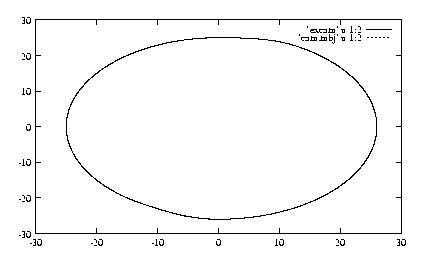
CAM PROFILE FITTED WITH SPLINE CURVE (OUTPUT)
Testing of code:-
For testing our profile synthesis method we are taking acceleration
values at regulear interval of theta for known displacement function
.We get
one profile . As displacement function is known we can directly calculate
cam
profile .The we can compare two cam profiles.
Spline code:
Step 1: Input set of points.
step 2: select cubic functinon a*u*u*u+b*u*u+c*u +d; (0<=u<=1)
step 3: Get Mspline which transforms geometric values to
the
polynomial coefficients.
| 2 -2 1 1
|
| -3 3 -2 -1
|
Mspline=
| 0 0 1
0 |
| 1 0 0
0 |
p(u)=[u*u*u
u*u u 1]* Mspline*
| Pk |
|Pk+1 |............................{A}
| PDk |
| PDk+1|
Step 4: Apply boundary condition to get derivative terms required
in the above
Condition 1:-First parametric derivative at the
junction of two successive
segments are equal.
Condition 2:-Second parmetric derivative is equal
at the junction of two
segments are equal .
Step 5:-Calculate all intermediate co_ordinates using A.
Step 1: Input is stepwise(descrete)
values of acceleration given by the
user.
Step 2: Using above values of
acceleration ,calculate displacement
values using induction method.
Mathematical Induction Method:
1) Taylor series:
y(x+delx)=y(x)+(delx)y'(x)+(del(x)*2)/2!*y''(x)+...............................(1)
y(x-delx)=y(x)-(delx)y'(x)+(del(x)*2)/2!*y''(x)-...............................(2)
3)
eqation(2)-eqation(1)= y'(i)=1/(2*h)* (delta(y))...............(3)
4)
eqation(2)+eqation(1)=y''(i)=1/(h*h)*(y(i-1)-2*y(i)+y(i+1))
5)
Adding all the terms,we get
y(n)=(1-n)yo+n*y1+ E((n-i)y''(i))
for n=2,3,4......(N-1)
This is the basis of synthesis equation.
Step 3: Using the theory of envelops[2]
we draw the cam profile as an
envelope tangent to all the roller positions.
ENVELOPE TANGENT TO ALL THE FOLLOWER POSITIONS
Results:-
Results for S H M.
RESULTS FOR STEP CAM


Conclusion:- As shown in result there are two cam profile
one is exact cam profile obtained directly from formula for SHM .Second
cam profile is obtained after profile synthesis. Both the profiles
are exactly matching. Thus metoh is correct.
Application:-
1. Spline code can be used
for drawing cubic spline passing through
the given set of points.
2. Cam profile can
be generated for given acceleration curve.
References:-
1. CAM DESIGN AND MANUFATURE by
Preben W. Jensen
2. MECHANICS AND DESIGN
OF CAM MECHANISMS by Fan Y. Chen
3. GEOMETRIC MODELLING by
Mortinson
4. AN INTRODUCTION TO SPLINES
FOR COMPUTER GRAPHICS AND
GEOMETRIC MODELLING. by Bartels.