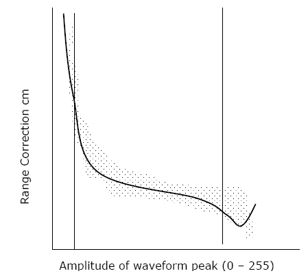

Figure 14: Range calibration curve(Modified after Ridgway et al, 1997)
This method aims at applying correction for range walk in range or in ToT measured by constant fraction method, as discussed above. The calibration data (time or range measured vs. amplitude of returned energy) are collected at a test site. The actual distance between sensor and target is known which is used to determine correction to time or range. The plot of correction versus amplitude of return pulse (Figure 14) is the calibration curve. The timings recorded by sensor are corrected by using the calibration curve for the measured values of return amplitude.