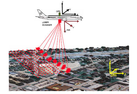
The Figure 3 shows the various sensors and scanning mechanism involved in LiDAR data collection. The basic concepts of airborne LiDAR mapping are simple. A pulsed laser is optically coupled to a beam director which scans the laser pulses over a swath of terrain, usually centred on, and co-linear with, the flight path of the aircraft in which the system is mounted, the scan direction being orthogonal to the flight path. The round trip travel times of the laser pulses from the aircraft to the ground are measured with a precise interval timer and the time intervals are converted into range measurements knowing the velocity of light. The position of the aircraft at the epoch of each measurement is determined by a phase difference kinematic GPS. Rotational positions of the beam director are combined with aircraft roll, pitch, and heading values determined with an inertial navigation system (INS), and with the range measurements, to obtain vectors from the aircraft to the ground points. When these vectors are added to the aircraft locations they yield accurate coordinates of points on the surface of the terrain.
Figure 3: Principle of topographic LiDAR
The principle of using laser for range measurement was known since late 1960s. At the same time people begun thinking about the use of airborne laser for measurement of ground coordinates. However, this could not be realized till late 1980s as determination of location of airborne laser sensor, which is a primary requirement, was not possible. The operationalization of GPS solved this problem. This is among the important reasons that why the laser mapping from airborne platform could not be realized before.
The LiDAR technology is known by several names in literature and industry. One may regularly come across the names like Laser altimetry, Laser range finder, Laser radar, Laser mapper and Airborne altimetric LiDAR. The term Airborne altimetric LiDAR (or Simply LiDAR) is the most accepted name for this technology.
The process of computation of ground coordinates is shown in the flow diagram (Figure 4)
Figure 4: Flow diagram showing various sensors employed in LiDAR instrument and the computation steps