
INDIAN INSTITUTE OF TECHNOLOGY KANPUR
Department of Materials and Metallurgical Engineering
Virtual Laboratories for Thermal Processing and Characterization of Materials
|
|
INDIAN INSTITUTE OF TECHNOLOGY KANPUR Department of Materials and Metallurgical Engineering Virtual Laboratories for Thermal Processing and Characterization of Materials |
|
Mechanical Testing Laboratory |
Tensile Sample Geometry
A typical cylindrical tensile sample is illustrated in the sketch below:
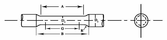
The important dimensions to measured prior to a tensile test are given below.
Two marks are made within the uniform section (i.e., gauge section) A. The distance between these two gauge marks, denoted as G in the figure above, is called the gauge length.
The diameter, D1, of the gauge is measured to calculate the area of cross-section. An average several values of the diameter are taken.
Overall, the dimensions D1, D2, B and R for the above tensile sample are as per some specified standard. For example, as per ASTM standard, A-370: A = 20 mm, B = 28 mm, D1 = 4 mm, D2 = 8 mm and R = 4 mm.
Tensile testing can also be done on plate specimen with a similar geometry as above (i.e., it will also have a reduced gauge section, etc.). In the case of the plate specimen the area of cross-section will have to be calculated by measuring the width and thickness of the gauge section.
What the world says about
gauge and
along with
tensile
Fastest
FTPS
anywhere,
Go FTP FREE
Client