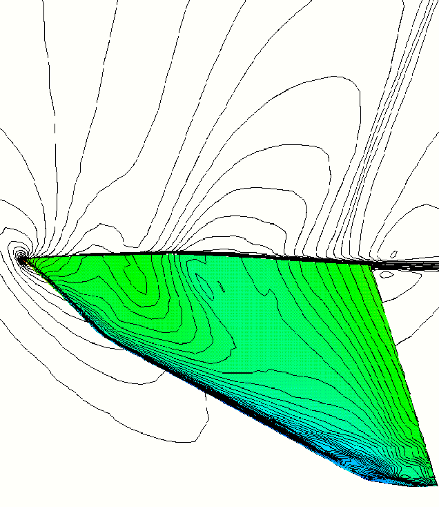
M=0.84, Re=10^6 flow past
Onera M6 wing at
Transonic flows past wings and airfoils
This
area of research is extremely vital to the design of transport and fighter aircrafts.
Figure 3 shows the computational results for Mach 0.84 flow past
an Onera-M6 wing at 6.06° angle of attack. A Baldwin-Lomax turbulence model
has been utilized for simulating turbulent flows. The lambda shock pattern on
the wing surface has been captured quite well. The flow past the wing of
the Light Combat Aircraft (LCA) designed by the Aeronautical Development Agency
(ADA) is shown in Figure 4. To the best of the knowledge of this
author, this is the first simulation of flow past the LCA wing using the
Navier-Stokes equations. The code has been ported on the computers at ADA,
Bangalore for use in their design and analysis activities. Figure 5 shows
unsteady flow past a NACA 0012 airfoil at 10° angle of attack.
M=0.84, Re=10^6 flow past

M=0.9,
Re=10^6 flow past
the LCA wing at ![]() =5.0°
=5.0°