3.5. Portable Pulsar Receiver (PPR):
Some pulsar observations may require data with high time
resolution limited only by the Nyquist sampling rate by the chosen band-width.
Also, in some applications it may be preferred to have a band-width studied
with very high frequency resolution to allow for finer de-dispersion correction
to study the details of micro-pulses and sub-pulses of strong pulsars.
In such cases, the base-band voltage signals may be digitized to one or
two-bits and recorded without any pre-processing using a high speed data
recorder. The recorded data may be processed off-line to perform operations
such as coherent de-dispersion, pulse folding, etc., using suitable computers.
To facilitate these types of observations modules developed for the pulsar
search pre-processor were identified, configured suitably and used in designing
a portable PC based data recording system.
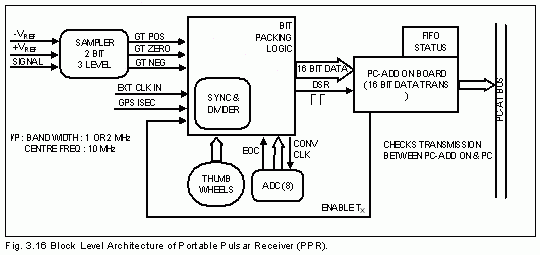
The PPR is equipped with a two bit 4-level quantizer (as
shown in figure (3.16)). To digitize the base-band signals, the quantizer
has

3 comparators with thresh-holds set at +Vt,
-Vt and 0 V respectively (where Vt can be set in
the range 2.5V to 0.2V). The comparator outputs then passed on to a encoder
to assign digital the form of zero-mean Gaussian noise voltage. The gains
in the receiver stages that precede the quantizer are so adjusted as to
fit the ±Vt thresh-holds at ±s respectively, of
the base-band noise.
|
|
|
||||
|
|
|
|
|
|
|
|
1 1 1 |
0 0 1 |
0 1 1 |
0 1 1 |
1 0 1 |
-Vref < Vin < Zero Zero < Vin < Vref Vin > Vref |
NOTE: Other combinations are not valid
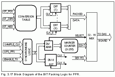
A bit packing logic (shown in figure (3.17)) packs 8 consecutive 2-bit samples into 16-bit words to match

the Bus-width of the Data Collection System (DCS). This reduces the output sample rate by the factor of 8. The counter based sequencer identifies 8 bit packing states to pack the samples and then latches the word to an output buffer. The sequencer also generates a write pulse for every output word that is transmitted along to the DCS. The separate counter produces a pulse for every 4096 output words. This pulse is used to trigger the set sequencer to generate an extra write pulse accompanying which a known 16-bit pattern is sent on the output data lines. This way, the recorder gets a marker word after every block of 4096 data words. This will be useful during post-processing to identify blocks of data with missing or extra data words. The 16-bit marker pattern has its top byte filled with zeros and the lower byte consisting of actually the output of another 8 bit counter that counts the number of such blocks of 4096 samples (module 25%). The bit packing and marker generation functions are designed into a single EPM7128 (15ns) EPLD. The outputs are driven to the DAS using TTL differential buffers. The clock for the bit packing logic is derived from a suitable oscillator through a programmable counter so that the sampling speed may be varied. Before starting to sample the data the timing logic waits for the DAS to give an "Enable Transmission" signals on the on-set of 10sec pulse from a global positioning system (GPS) interface (Chanthrasekaran, 1995). This synchronization is necessary in cases when simultaneous observations are to be conducted at different sites. The synchronization ensures that the start of observation defined at the start time in the format of xx.yy.zz (hours.minutes.secs) where zz may be 00, 10, 20, 30, 40, 50.
The PC time is synchronized to the observatory clock periodically.
At the start of an observation the DAS locks the starting time and enables
the bit packing logic through the "Enabled Transmission" line. At the on-set
of the next 10second pulse from the GPS interface the data starts flowing
into the DAS FIFOs and gets recorded on to the hard disk. The limiting
factor for acquisition speed is set only by the hard disk access time.
With this system, the maximum sustained rate of recording corresponds to
about 0.75 Mbytes/sec corresponding to recording of 1.5 MHz band-width
with 2-bit digitization at Nyquist rate.
Post-processing:
The recorded data is extracted and searched for the marker pattern in order to identify any slips that move its location during recording. The missing samples are inserted with equivalent samples of random noise (this does not affect the signal statistics significantly since the fraction of the data missed due to slips is expected to be less than 0.01%). This process can thus tag the obsolute time associated with the train of samples correctly.
The data is then Fourier transformed to produce narrow channels of optimized band-width based on the DM to be corrected. Incoherent de-dispersion is performed on the complex frequency spectra as explained in section (2.1.). The de-dispersed spectra are then collapsed to form a single channel and synchronously folded over the pulse period to achieve the required enhancement in signal-to-noise ratio.
This technique has been used and several observations
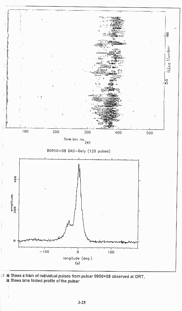
have been conducted at ORT. Figure (3.18) shows the profiles of these observations.
Figure(3.18a) shows a train of indiviudal pulses from pulsar 0950 ±
08 observed using the Ooty Radio Telescope with a base-band width of 1
MHz. Figure(3.18b) is a de-dispersed, time folded profile of pulsar 0950+08
observed with the same set-up. Several pulsars have been observed successfully
using the portable pulsar receiver at Mauritius Radio Telescope (Nalini
Issur, 1997). Currently a paper is being written for publication describing
the systems and the test results.
