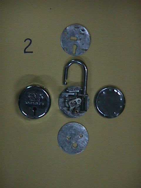
INSIDE THE CASING
Every lock is provided with an external casing which provides it an elegant
look. After removing the external casing, one can observe the internal casing
which press-confines the internal parts. After removing the internal casing
too, one can observe the internal structure of the lock as shown in fig.
MAIN PARTS OF A LEVER LOCK
* A u-shaped spring loaded hook with a half cut slot at one end.
* A locking or stoping plate which engages with the slot in the hook to "lock" the lock.
* SEVEN LEVERS:-
- Main lever (lever 1) provided with a projecting pin (stop) and slots at both the sides.
- Lever 2 (spring loaded, notched)
- Lever 3 (spring loaded, notched)
- Lever 4 (non spring loaded, unnotched)
- Lever 5 (non spring loaded, unnotched)
- Lever 6 (spring loaded, notched)
- Lever 7 (spring loaded, notched)
* Key which is provided with seven cuts & projections.
NOTE:-
- Generally levers ( lever 2 to 7 ) have a slot inside them.
- Spring loaded levers are notched on the inside of the slot.
- Non spring loaded levers do not have any notch.
- The undersides of each lever may be uniquely shaped and ordering of
levers in different locks is different to make them unique.
- Key is provided with cuts and projections corresponding to the
variously shaped undersides of different levers.
- The motion of the engaging plate is controlled by the main lever.
BACK
NEXT
