A) Grain Boundary Engineering
The concept of Grain Boundary Design and Control was first proposed by Prof. Watanabe in 1984, to limit the undesirable effects of inter-granular degradation in alpha brass.
Over the years, the concept has come to be known as Grain Boundary Engineering (GBE).
This engineering of grain boundaries can be described as a process in which the geometry of grain boundaries is altered in order to obtain higher fraction of grain boundaries with desirable properties.
▶ More details
In general, desirable properties are associated with boundaries having low energy structures. Such low energy structures, special boundaries, are described geometrically by a low sigma number, Sigma (Sigma < 29), which is defined as the reciprocal of the fraction of lattice points in the boundaries that coincide between the two adjoining grains. Coincidence Site Lattice (CSL) boundaries are characterized by specific values of misorientation angles between the neighboring grains which allows the lattices to notionally coincide. The boundary plane matters, in addition to the misorientation; this means, in effect, that only symmetric pure tilt or pure twist boundaries are likely to have a higher density of CSL points. Such boundaries usually have lower free volume than random high angle grain boundaries (HAGBs) and are hence more resistant to intergranular degradation.
GBE has been shown to improve certain properties of low stacking fault energy FCC materials such as microalloyed steels, austenitic steels, copper, nickel alloys and lead alloys. It can be used to improve resistance to various forms of intergranular degradation creep and cavitation, corrosion and stress corrosion cracking, and embrittlement wherein lies the motivation for this work. Inconel 600 is a standard nickel based superalloy for applications involving high temperature operation and corrosion resistance. It is used extensively in the chemical industry evaporator tubes, flaking trays, equipment for handling abiotic acid; aeronautical field engine and airframe components; tubings in nuclear reactors due to excellent resistance to corrosion by high purity water etc.
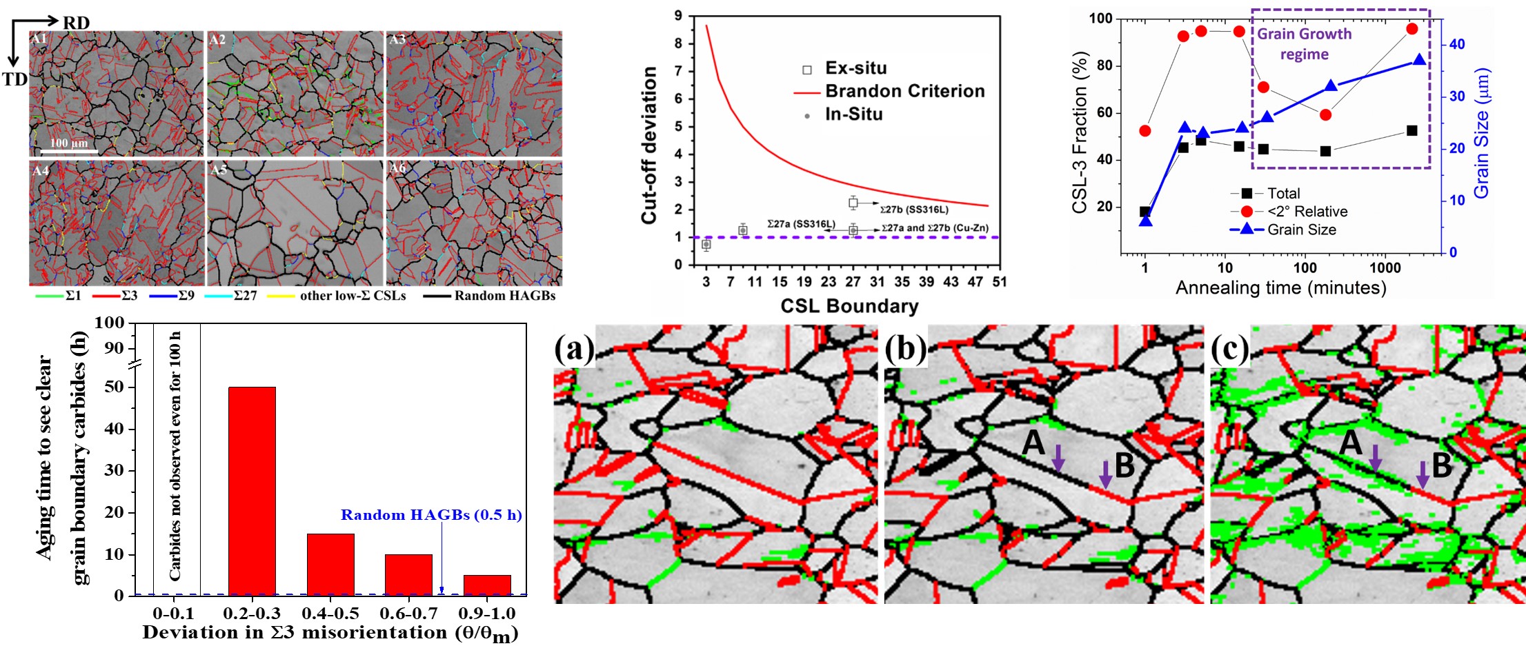
Our research on Grain boundary engineering has led to the some important conclusions. Firstly, our results have shown that hot rolling can be used as a cost-effective and technologically easy to implement technique to improve the GBCD in polycrystalline materials. For Inconel alloy, the total low-Σ CSL fraction (3≤Σ≤29) increased to 77% consisting of mainly Σ3 boundaries (64%) and just 1% Σ1 boundaries for A3 sample condition. Another important conclusion from our research is that most of the Σ3 boundaries, around 93% lie within the ‘θ/θm’ range of 0-0.1 illustrating that A3 is the most suitable sample condition to achieve an optimized grain boundary engineered microstructure. Our research has also shown that cut-off in deviation to define the specialness of Σ3 boundaries is musch less than that defined by Brandon's criterion and hence one should be careful while choosing a limit to calculate the special boundaries. Lastly, we have also deveoped a method by which one can identify and also remove the errors involved in the measurement of misorientation using EBSD.

Figure 1: Grain boundary engineering in Inconel 718, Cu-Zn alloy and 316L Stainless steel
B) Structural Nanomaterials
B1) Microstructural and Mechanical Behavior during Constrained Grooved Pressing (CGP)
Nanostructured materials or ultrafine grains (UFG) are profoundly known to display enhanced mechanical properties like hardness and strength.
There are different approaches to manufacture these types of materials predominantly by severe plastic deformation (SPD) which in turn can be achieved by methods like constrained groove pressing (CGP),
accumulated roll bonding, equal channel angular pressing/extrusion, high pressure torsion, cyclic extrusion compression, twist extrusion.
▶ More details
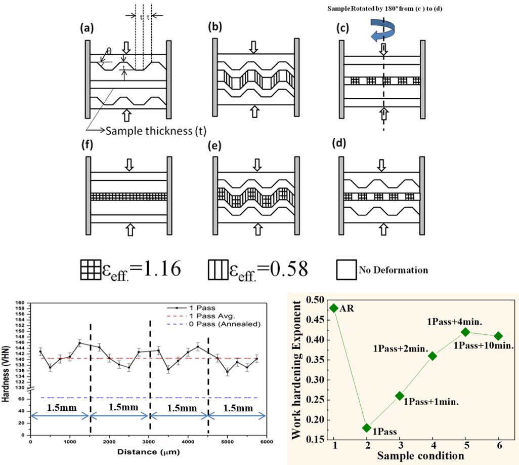
CGP allows us to introduce theoretically uniform and large cumulative equivalent strain to the materials through repetitive shear deformation by using alternate pressing with an asymmetrical grooved and flat die while maintaining a gap between the lower and upper die equal to the thickness of the sample. This helps to maintain only pure shear deformation under the plain strain deformation condition. Using this method, a uniform cumulative strain of 0 - 3.48 (each CGP pass imposes strain magnitude of 1.16 are introduced to the copper-zinc alloy sheets to produce high strength Nano-structured materials). For these SPD processed samples material characterization were done using Optical microscopy, Scanning electron microscopy, Electron back scattered diffraction technique (EBSD), X-ray diffraction technique (XRD) and mechanical testing by Universal testing machine (UTM) and micro-hardness testing machine etc. These techniques help in understanding the grain boundary engineering (GBE) of the processed CGP samples. The most pertinent application of the GBE is resistance to degradation, improving creep and cavitation resistance, embrittlement in the material as well as corrosion at the grain boundary. The objective of this research is to produce fine grain structure material by CGP process for enhancing the mechanical property for high strength application and also to understand the micro mechanism of these SPD process to correlate the effect of type of grain boundaries on mechanical properties of the materials.

Figure 2: CGP process and corresponding mechanical behavior
Our research on CGP process and its microstructural as well as mechanical characterization has led to some important conclusions. Firstly, analysis of the stress-strain plot showed that CGP sample and sample heat treated for 1 minute, fractured before attaining the ultimate tensile strength (UTS), which can be directly related to the presence of voids. On the other hand, samples given SHT of 2 minutes and above attained UTS and fractured beyond the strain corresponding to UTS. Strain hardening behavior of the various sample conditions showed that heat treatment of 2 minutes and longer duration, completely transforms the hardening behavior of severely deformed samples, and exhibit a three-stage strain-hardening behavior. This implies that a minimum fraction of recrystallization is required for healing of voids, to alleviate the problem of pre-mature fracture, and this minimum fraction was obtained from 2 minutes of SHT. Thermal stability results of the partially recrystallized samples show that these samples are stable up to 300 °C.
B2) Microstructural, Mechanical, Oxidation and Corrosion Behavior during Machining
Machining is known to impose large deformation during cutting and formation of chips.
Moreover, it also imposes similar large strains on the surface of the material that is being cut. However, the strain and strain-rate and the ensuing temperature rise, and the eventual microstructural transformations
that occur in the chip and the surface, are largely dependent upon the machining configuration. The final microstructure thus obtained, which determines the surface response of the material towards corrosion and
oxidation, is a function of machining parameters.
▶ More details
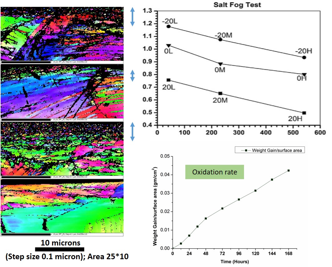
The aim of this work is to understand the surface-characteristic responses of machined samples of different kinds of steels. Mild steel, austenitic stainless steel and duplex steel were subjected to machining at various rake angles (-20?, 0?, +20?) at varying speeds, while keeping other machining parameters constant. Microstructural characterization of machined samples were carried out using XRD, optical micrography, SEM. Tribological characterization like roughness and texture of the of the samples were studied. Mild steel and austenitic stainless steel sample were subjected to immersion, dynamic polarization and salt fog tests at ambient temperature to study the corrosion behavior of differently machined samples. On the other hand, mild steel and duplex steel were exposed to isothermal oxidation experiments at temperature ranging from 50 to 700 C to study the oxidation kinetics and mechanism of oxidation as a function of machining condition.

Figure 3: Microstructure, Corrosion and Oxidation results for various machining configurations

