Research
Research Areas
My research interests are in the field of integrated circuit and system design - involving both analog, digital and mixed-signal circuits. Currently, my focus is on circuits that synthesize/sense/process frequency and delay. This includes a basket of diverse circuits - oscillators that can synthesize a frequency, phase-locked loops (PLL) that can multiply and clean up a jittery clock, delay-locked loops (DLL) that generate a stable delay, time-to-digital converters (TDC) that can digitize pico-second time intervals, and various delay-tuning circuits. The applications related to these are endless - ranging from the TDC used in the frontend electronics of an experimental physics lab to the 20-30 PLLs used in a modern mobile processor.
Research in this area generally has the following outline. We identify a specific challenge in the area - say, generation of a cleaner clock or high-resolution delay tuning (of course, we'll put numbers to define "cleaner" and "high-resolution"). Once the design challenge is identified, we come up with solutions to address it. The proposed solutions are analyzed through numerical methods for the first level of verification. Then the circuit that implements the solution is designed and simulated through CAD tools. This circuit is then fabricated through foundries and tested. The measured, simulated, and theoretical results are expected to match for thorough and rigorous research work. If it doesn't, we figure out the reason for the discrepancy and repeat the process. Good research is when the proposed solution solves the identified problem and redefines state of the art.
Depending on your duration with the group, you may get to do all of these stages (M.S/Ph.D) or part of them (MTech/BTech/project associates/interns). The more "smart, hard work" you do, the more you get to learn.
I am looking for motivated students who can push the boundaries of these research areas. If you are interested in working in the above or related areas, please mail me at chithra@iitk.ac.in with your resume.
Prior research:
A brief overview of some of my prior research is given below. Please refer to the publications for more details.
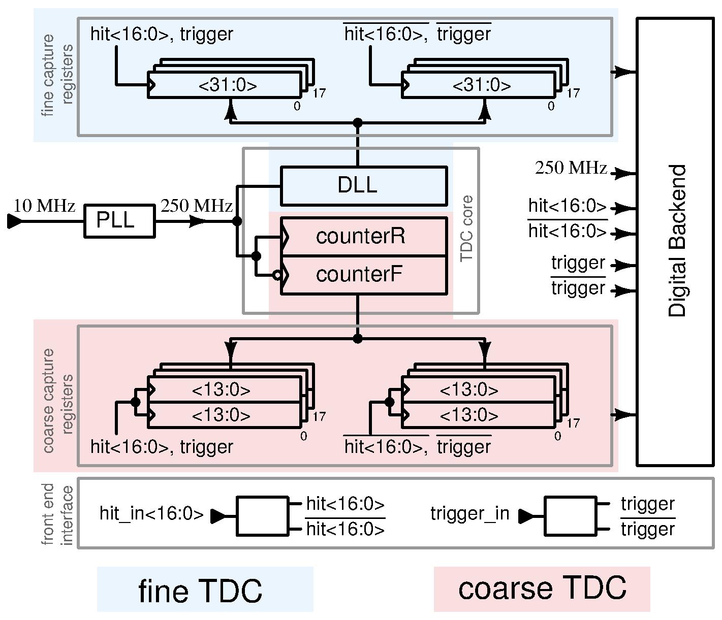
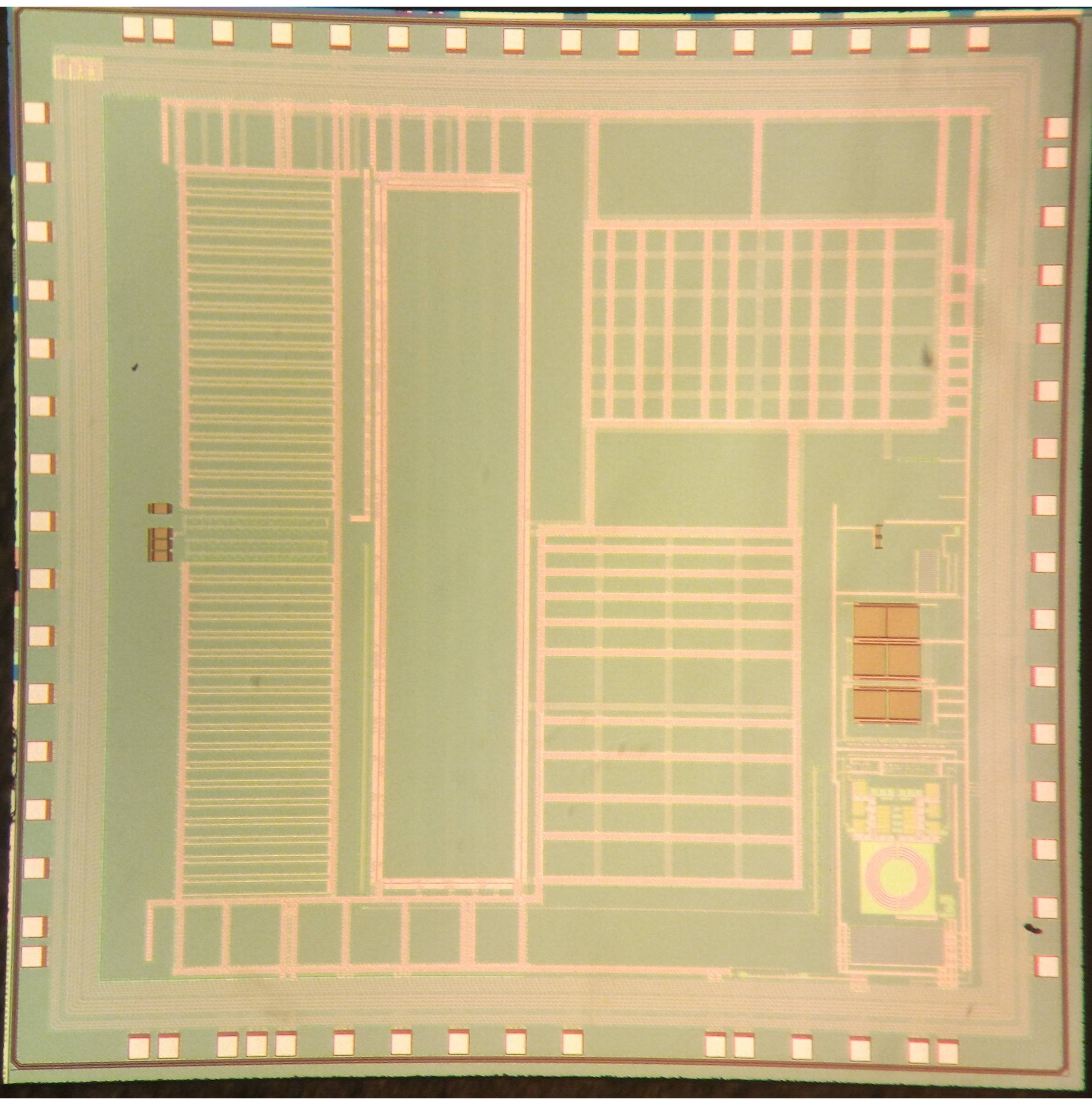

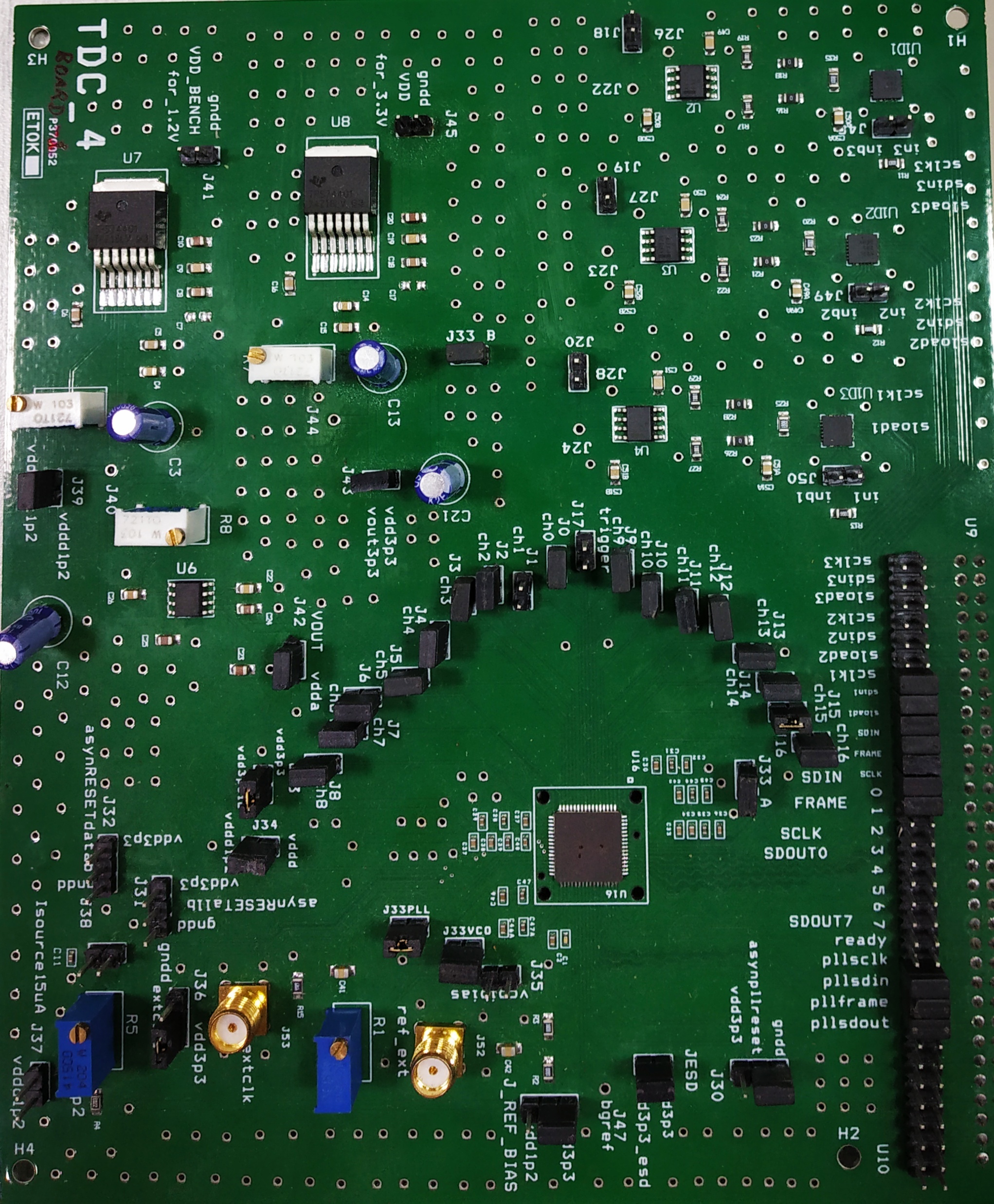
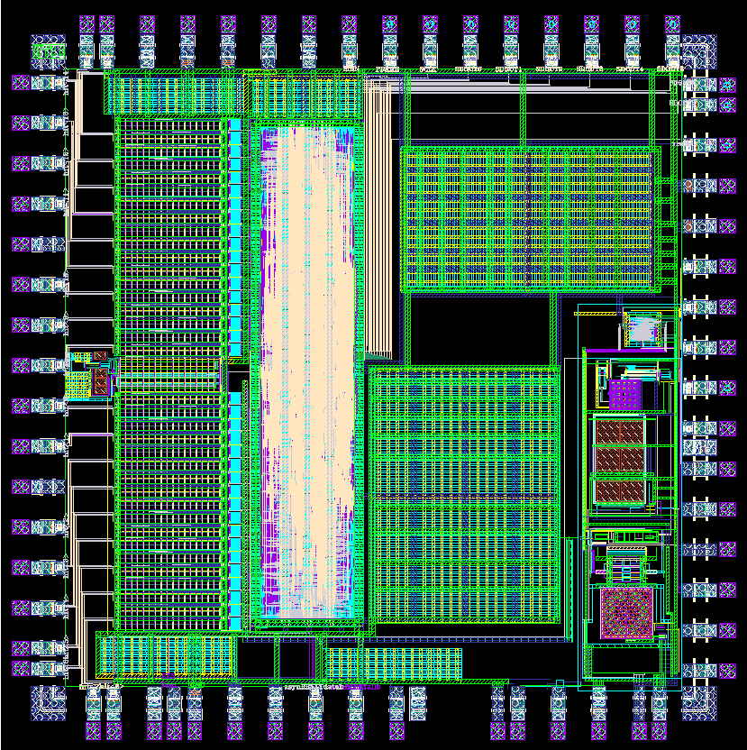
Time-to-digital converter with 125 ps resolution for the India-based neutrino observatory
India-based neutrino observatory is an experimental lab that is being set up for studying about neutrinos. An 18-channel time-to-digital converter (TDC) is required in the observatory to record the time instants at which these particles are sensed within the detector. The TDC has a resolution of 125ps and a dynamic range of 65.5μs. The TDC core consists of a delay chain stabilized by a delay-locked loop (DLL) and synchronous counters. The TDC prototype designed in 0.13 μm CMOS process achieves a single-shot precision better than 65 ps. The measured differential nonlinearity (DNL) varies from −0.27 LSB to 0.21 LSB, while integral nonlinearity (INL) varies from −0.19 LSB to 0.25 LSB. The TDC occupies an active area of 3.72 mm^2 and consumes 3.4 mW per channel.
Static phase offset reduction techniques for delay-locked loops
Static phase offset (SPO) is a nonideality in delay-locked loops (DLLs). It causes spurs during frequency synthesis using multiplying DLLs (MDLLs), DNL/lNL error in DLL-based TDCs, skewing errors in clock distribution networks, and errors in the generation of different clock phases.
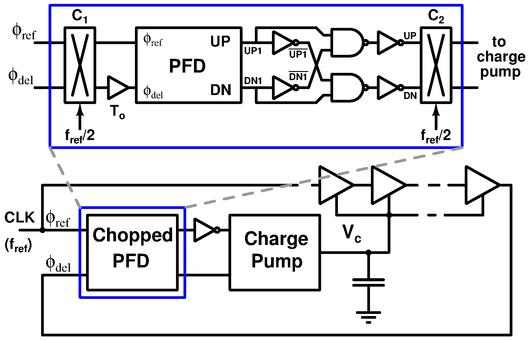
Proposed technique based on chopping.
The first solution I proposed extends the benefits of chopping the phase-frequency detector (PFD) to the charge pump by modifying the chopped PFD circuit. This method guarantees at least a 2x reduction in the SPO due to mismatches in the charge pump.
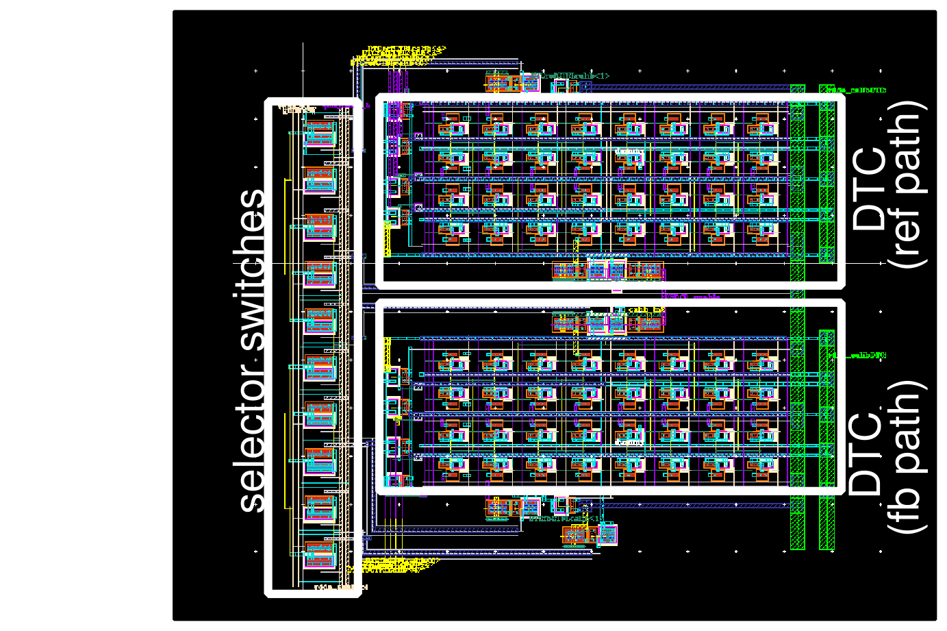
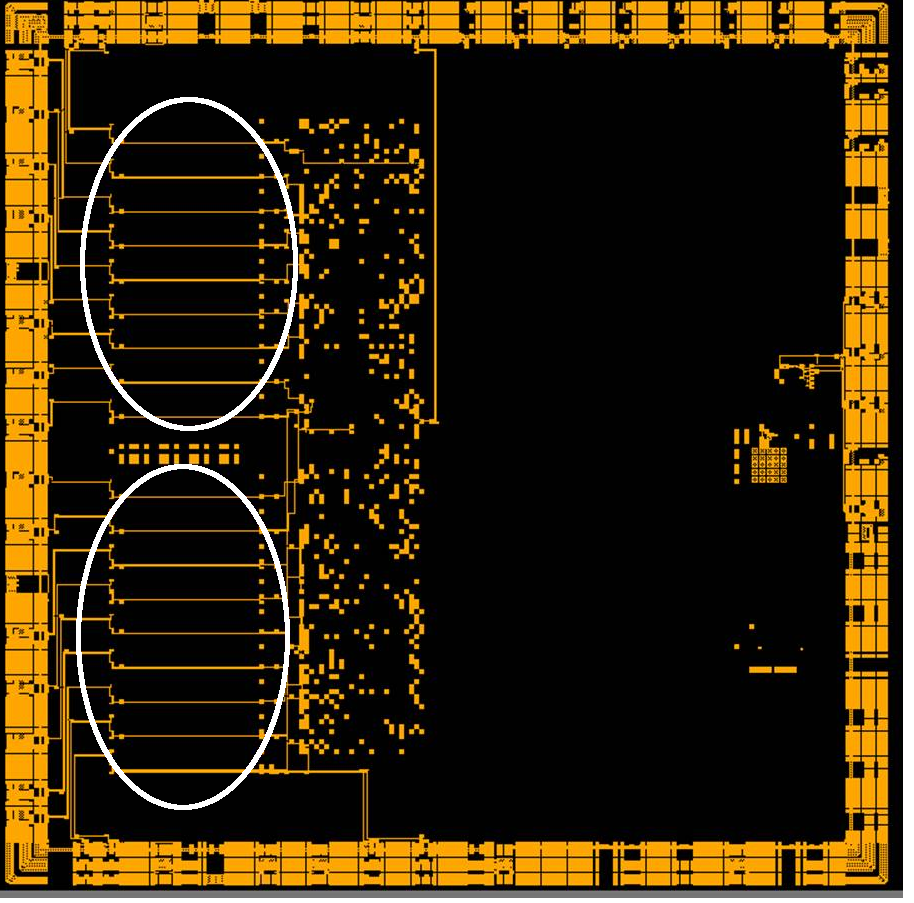
The second solution employs a self-calibrated, digitally programmable sensing circuit that can measure both the polarity and the magnitude of the SPO. The SPO is suppressed by tuning a pair of digital-to-time converters (DTCs) at the input of the PFD. Monte Carlo simulation results show that the SPO in a conventional DLL implementation improves from 12.44 ps to 0.82 ps when the proposed auto-zeroing technique is employed.
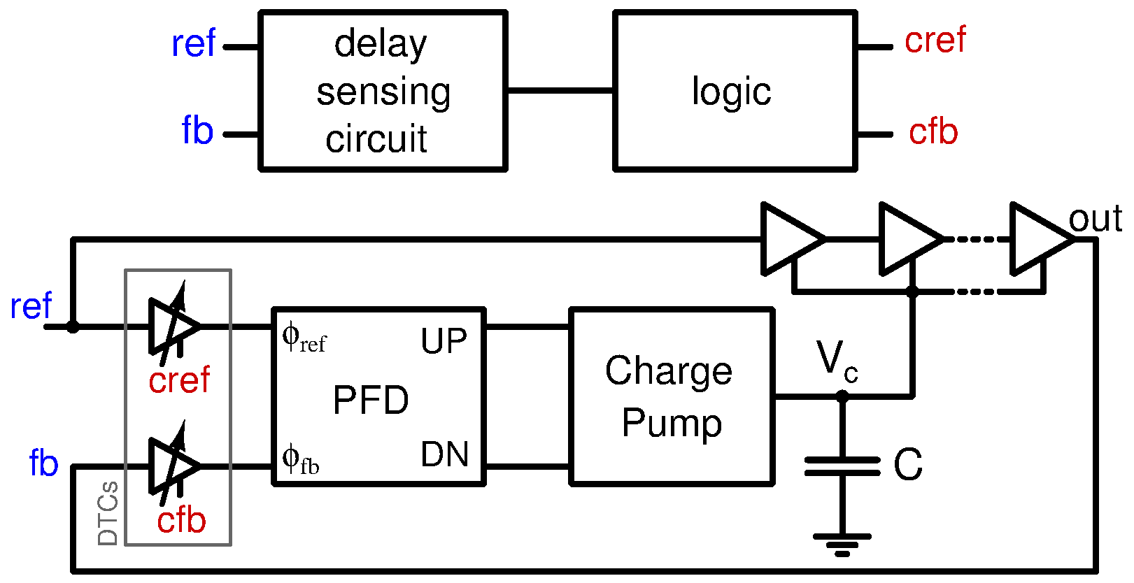
Auto-zeroing static phase offset.