Vapour Compression Cycle
Specific volume range in which the compressor works is much larger than the specific volume rang in which the expander works.
Hence work done by the expander is much smaller than the work done by the compressor.
Expands is replaced by a throttle valve. The schematic diagram of vapour compression refrigeration system is shown in Figures 31.2 (a) and (b):
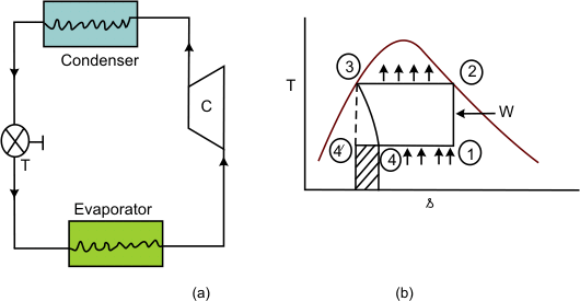
Wet refrigerant vapour enters the compressor at state 1 and undergoes isentropic compression to state 2.The compressed vapour enters a condense where it rejects energy as heat to ambient atmosphere and leave as saturated liquid at state 3, The saturated liquid then undergoes throttling through a valve to state 4. During the throttling process, the liquid partially vaporizes and attains the same temperature as that of the evaporator. The liquid vapour mixture then passes through the evaporator and comes out at state 1.
Energy removed from the cold body
 |
(31.4) |
Work done
 |
(31.5) |
 |
(31.6) |
Since the throttling process is isenthalpic,  But the process is irreversible, therefore  . If the expansion of the liquid in state 3 is conducted reversibly, the final state will be . If the expansion of the liquid in state 3 is conducted reversibly, the final state will be  . The amount of energy removed as heat from the cold body is . The amount of energy removed as heat from the cold body is  . Because of the irreversibility, the energy removed from the cold body is , Hence the shaded area . Because of the irreversibility, the energy removed from the cold body is , Hence the shaded area  represents the loss of the refrigeration effect. represents the loss of the refrigeration effect.
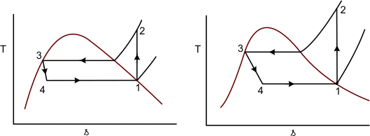
In the ideal refrigeration cycle, the refrigerant shown as leaving at state 1 is a mixture of liquid and vapour. However, in some cases, it is possible that the refrigerant leaves the evaporator as a saturated vapour or superheated vapour. In such cases, the refrigeration cycle appears as shown in Figures 31.3 (a) and (b)
|

 and
and 