


Experimental Setup
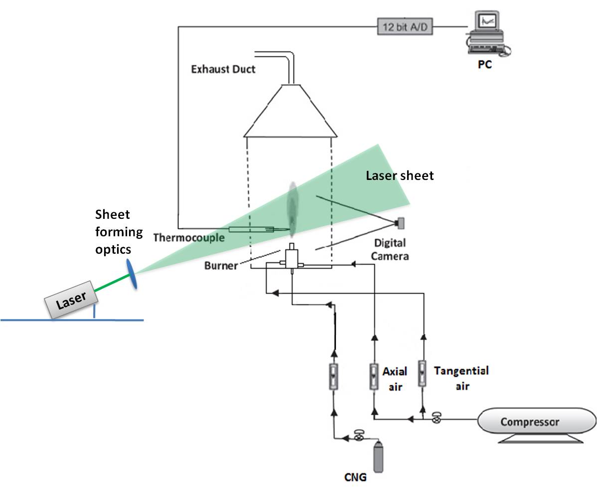
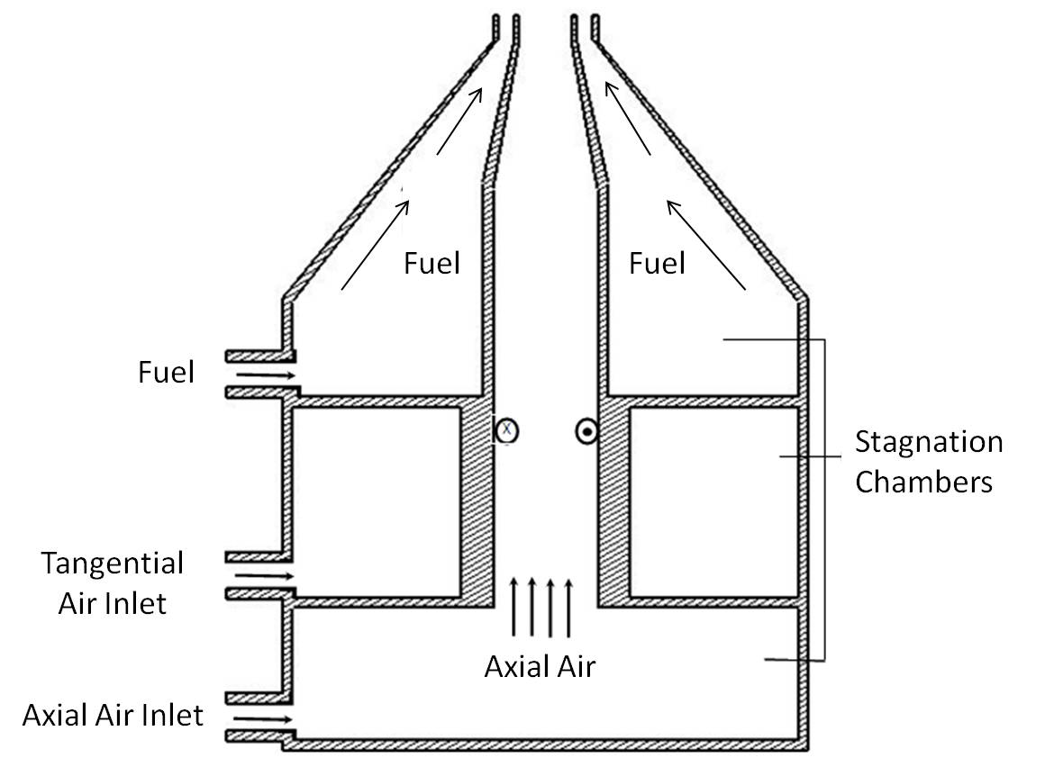
Burner Schematic
- The burner is kept in an enclosed chamber to avoid the entrainment of ambient air.
- Three burner inlets:
- axial air inlet
- tangential air inlet
- fuel inlet
- Calibrated rotameters are used to measure the flow rate of fuel and air supplied to the burner.
- The supply air and fuel are controlled through needle valves fitted just before the rotameters.
- Screens are provided before the burner exit to remove the nonuniformities in the inlet flow.
Experimental Procedure
- Open the main air inlet valve.
- Set the desired pressure by adjusting the inlet pressure regulator.
- Now open the needle valve and set the desired axial and tangential air flow rates.
- Vary the fuel flow rate and maintain the airflow rate constant.
- Then ignite the mixture at the burner exit.
- Wait for sometime till no further changes in the flame shape is observed.
- Ensure that the camera is aligned properly to avoid systematic errors.
- Acquire the flame image through the imaging system.