


Image Processing
- The flame videos obtained are converted to frames using video to still image convertor software.
- The frames are analyzed using image processing software called ImageJ. The still images of the flame are processed by various techniques such as Enhance contrast and Edge detection for exact identification of flame tip from the nozzle rim.
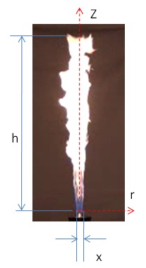
- The number of pixels of the flame image in the vertical direction along the centerline from the burner rim to the point where the flame is visible is counted and is scaled with the known dimension, say, burner rim diameter to obtain the exact flame height.
Flame Visualization
-
To play video
click here
Variation of flame height with MFR for LPG-air IDF
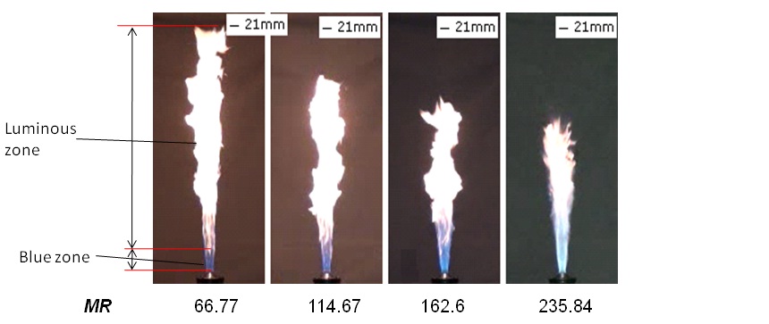
Flame height decreases with an increase in the Momentum Ratio (MR).
Visible Flame Appearance with MR for LPG-air IDF
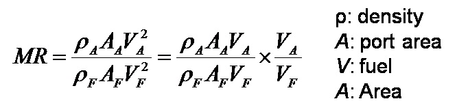
- Momentum ratio (MR) is defined as the ratio of momentum between air jet and the momentum of fuel jet.
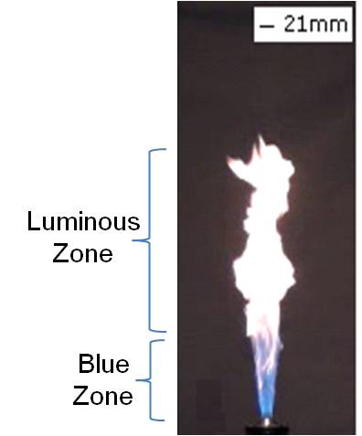
- The flame can be divided in two zones namely
- blue zone
- luminous zone (see figure)
- The blue emission is due to the radiation from excited CH* radicals in the premixed region at the flame base [1].
- The luminous zone is yellow due to the radiation from soot (carbon) particles.
Calculation of Visible Flame Height
 Sample calculation for obtaining the visible flame height of turbulent LPG air IDF for MR = 68.77 from single snapshot (see figure).
- The number of pixels in the vertical direction (along the centerline) from the burner rim to the point where the flame is visible (h) = 180 pixels
- Number of pixels of the burner diameter in the snapshot (x) = 7 pixels
- Actual dimension of the burner diameter (df) = 21 mm
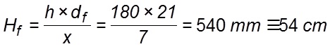
- Scaling of the actual flame height (Hf) becomes
- Therefore, actual visible flame height can be obtained from the above expression as
Temporal Variation of Visible Flame
To play video click here
-
Variation in visible flame height with time for MR = 66.775
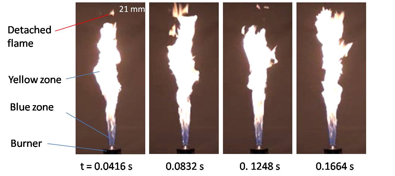
- Variation in visible flame height with time for MR = 66.77 is shown (see above figure).
- Undulations of the flame tip is observed from the time resolved images.
- The flame tip fluctuations occur due to buoyancy induced vortices shedding around it.
- As a result of local quenching, detached flame can be observed sometimes at the flame tip.
Error Analysis of Visible Flame Height
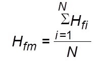
- Mean flame height (Hfm) is obtained from the average of the actual visible flame height of N flame images taken for analysis.
- The deviation from the mean flame height is obtained using the following formula
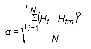 s: standard deviation of the flame height obtained from flame snapshots
Hfi: flame height of the ith image
i: index varying from 1 to N
Hfm: mean flame height
N: total number of flame images (26 in the present experiment)
Flame height is reported as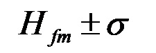
Sample Calculation for Visible Flame Height
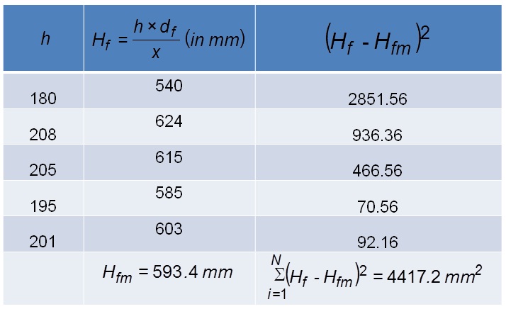
- Sample calculation for obtaining the visible flame height of turbulent LPGair IDF for MR = 68.775 from 5 flame snapshots is shown.
- A total of 26 snapshots were processed for finding the visible flame height at a particular MR in the present study.
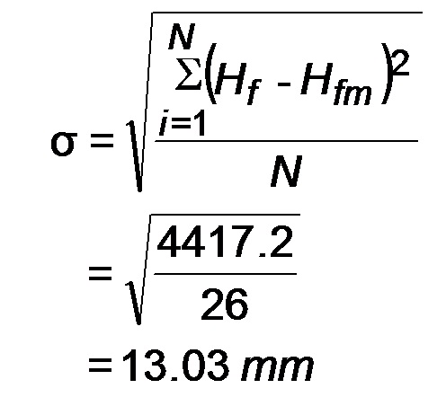
- The flame height is reported as 593.4 +- 13.03 mm where 13.03 mm denotes the deviation of flame height above and below the mean flame height. The Student t-distribution can be used when the number of flame images (i.e. sample size) taken for analysis is very small.
Variation of non-dimensional flame height with MR
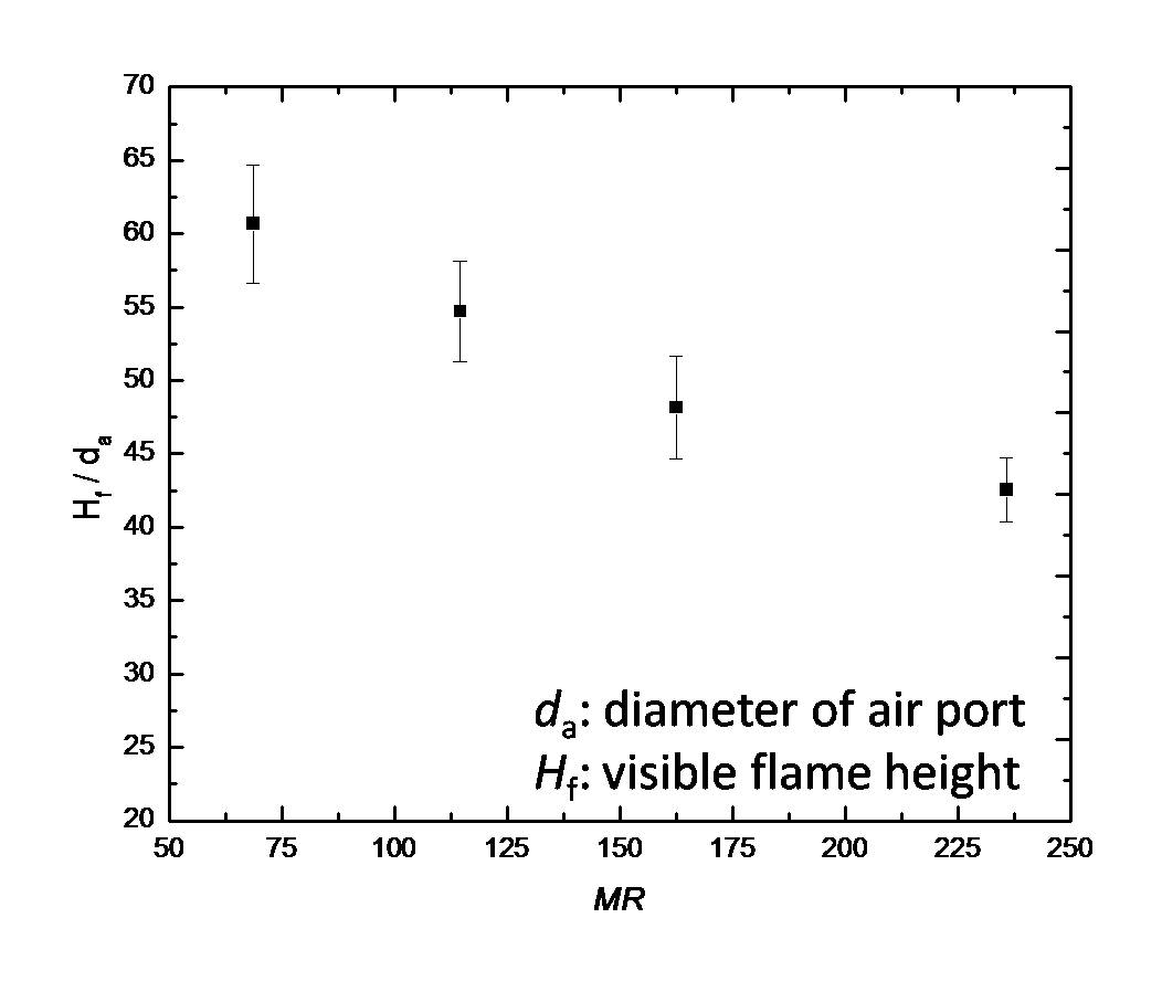
- The visible flame height (Hf) normalized by the diameter of air port (da) is found to decrease linearly with MR.
- An increase in central air jet momentum causes more entrainment of fuel along with the ambient air.
- Turbulent mixing is enhanced by the high momentum air jet which helps in faster consumption of fuel in flame zone.
- Turbulent mixing results in the formation of local premixing zone at the flame base known as the blue zone.
- The luminous zone is formed due to the presence of fuel rich region with radiation from soot particles.
Correlation of non-dimensional flame height with MR
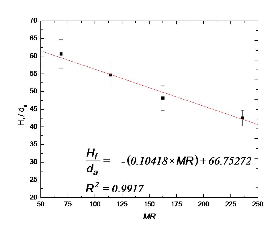
- The non-dimensional flame height of LPG IDF is linearly correlated with MR using the linear regression analysis.
- This empirical relationship will be helpful in the design of compact IDF based combustion systems.
- Students are encouraged to explore this relationship further using the graphical simulation utility.