


Variation of CNG Jet Diffusion Flame Height with Fuel Flow Rate
To play video click here
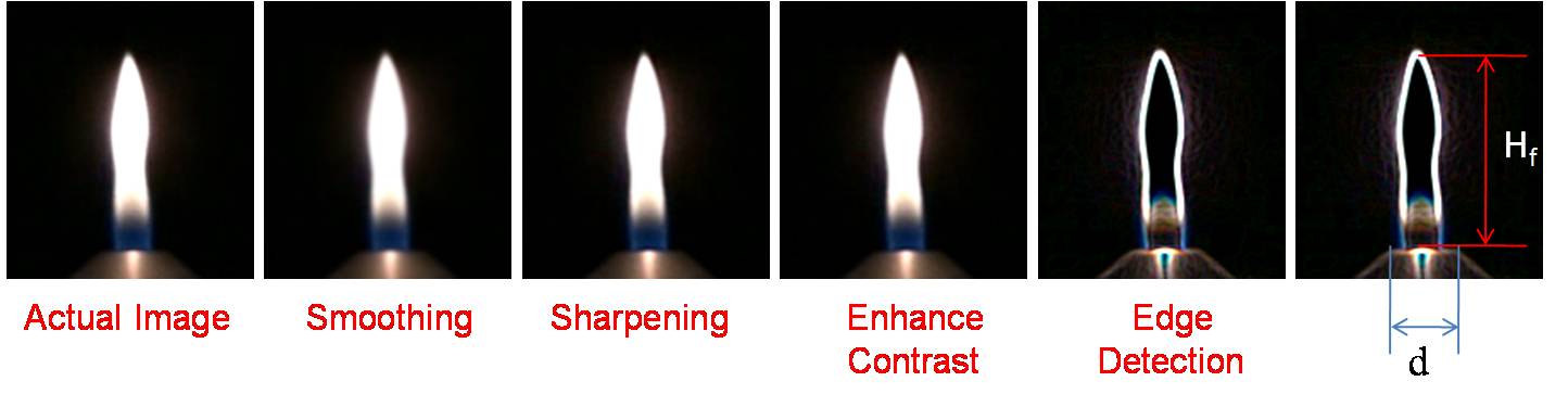
Image processing
- The flame videos obtained are converted to frames.
- The frames are analyzed using open source image processing software ImageJ.
- The still images of the flame are processed using Smoothing, Sharpening, Enhance contrast, and Edge detection steps for exact identification of flame tip from the nozzle rim.
- The number of pixels of the flame image along the flame centerline from the burner rim is counted and is scaled with the known dimension, the burner rim diameter, to obtain the jet flame height.
Variation of flame height at different volumetric fuel flow rates
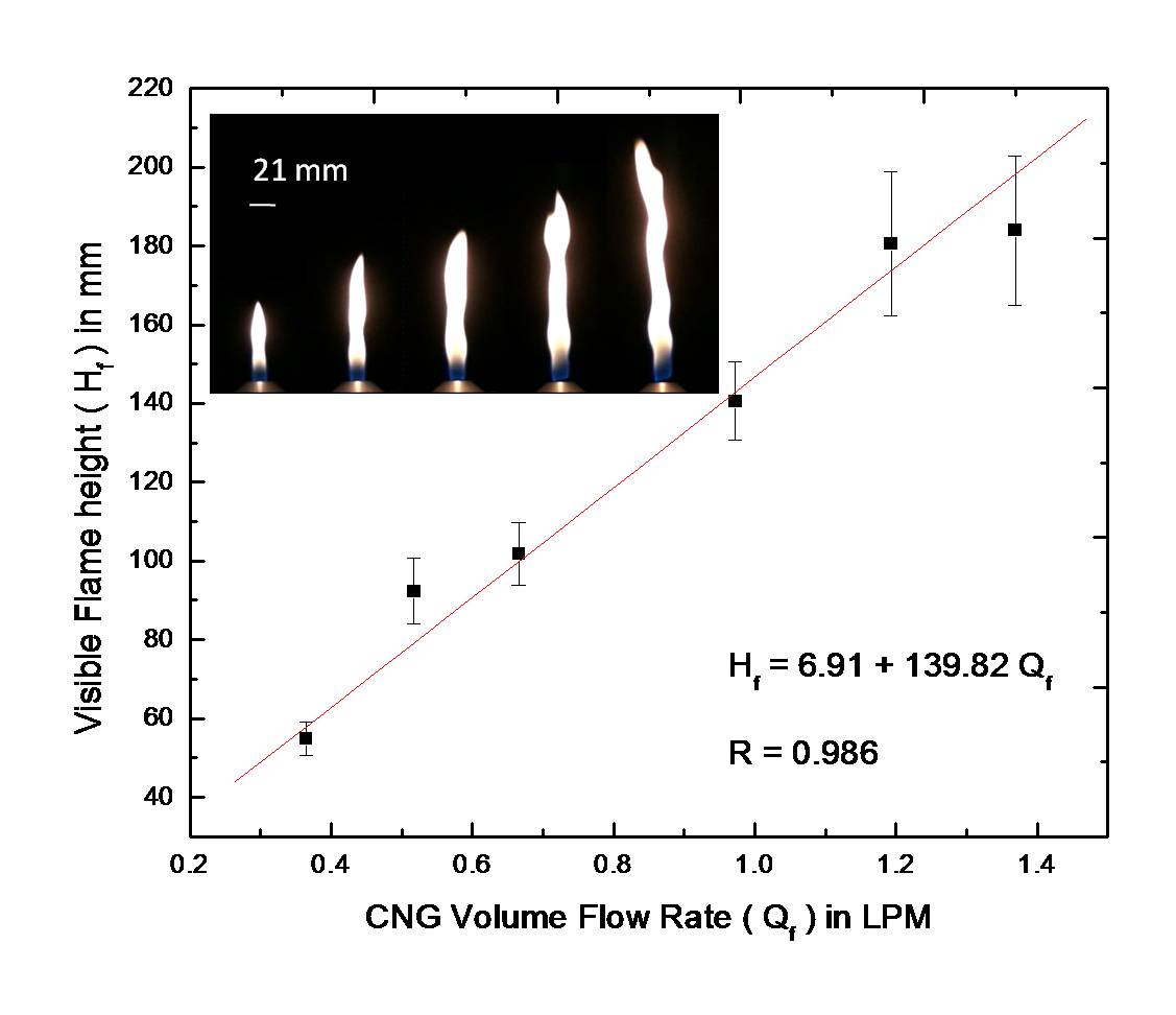
- Visible flame height (Hf) increases linearly with fuel flow rate (Qf).
- Although the experimentally obtained relationship does not follow the phenomenological relationship derived earlier, the analysis correctly predicted the linear relationship.
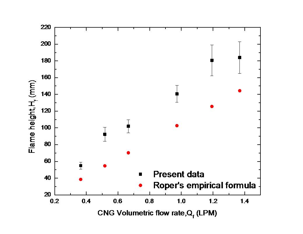
Comparison with Ropers empirical formula
Ropers empirical formula
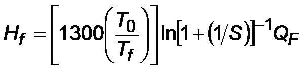
where
T0: ambient temperature
Tf : characteristic temperature for calculating diffusivity (1500 K)
QF : volumetric flow rate of fuel
S: air-to-fuel volume ratio for complete combustion
- More uncertainty at larger QF due to the increase in buoyancy around the flame front which makes the flame tip to oscillate.
- The Ropers empirical formula is found to underpredict the experimental value due to the assumed Tf.
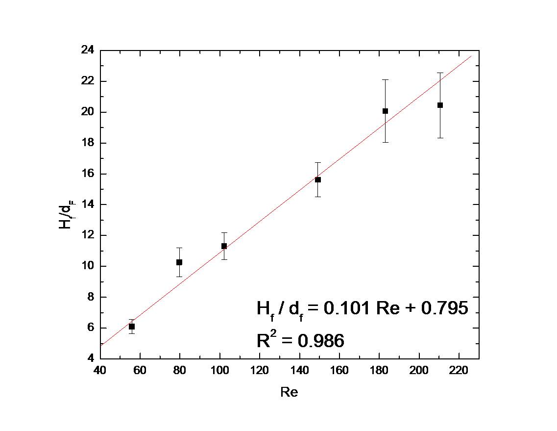
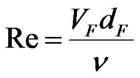
Variation of Flame Height with Reynolds Number
Where
Re - Reynolds number
VF - Fuel jet velocity
ν - Kinematic viscosity of fuel
dF - Diameter of the burner exit
- The experiments yield a relationship between non-dimensional visible flame height and flow rate in terms of Reynolds number.
- Students are encouraged to explore this relationship further with the help of graphical simulation utility.